
4D v16.3
Using output control lines
- 4D Design Reference
-
- Output forms and reports
-
- Overview
- Output forms
- Forms for printed reports
- Using output control lines
- An example report
- Creating mail-merge documents
- Creating labels
 Using output control lines
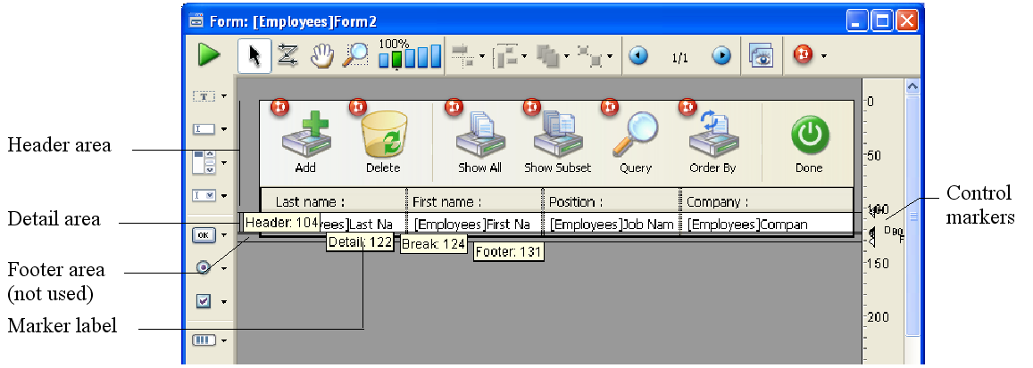
You control the Header, Detail, Break, and Footer areas with the output control lines in the Form editor. You move the control lines vertically to allow more or less space for each area. Any object that you place in these areas is displayed or printed at the appropriate location.
Here is how these areas work when the form is displayed or printed in Application mode, or using the integrated functions of the Design mode.
- Header area: The Header area is displayed at the top of each screen and is printed at the top of each page of a report. The Header area is defined as the area above the Header control line (H). You make the Header area smaller or larger by dragging the Header control marker vertically. You can use the Header area for column names, for instructions, additional information, or even a graphic such as a company logo or a decorative pattern.
You can also place and use active objects in the Header area of output forms displayed as subforms, in the records display window or using the DISPLAY SELECTION and MODIFY SELECTION commands.
All active objects can be inserted. This includes:- Buttons, 3D buttons, highlight buttons, picture buttons,
- Combo boxes, pop-up menus/drop-down lists, picture pop-up menus and hierarchical pop-up menus,
- Scrollable areas, hierarchical lists, list boxes
- Radio buttons, 3D radio buttons, picture radio buttons,
- Check boxes, 3D check boxes,
- Thermometers, rulers, dials.
- Detail area: The Detail area is displayed on the screen and printed once for each record in a report. The Detail area is defined as the area between the Header control line and the Detail control line (D). You make this area smaller or larger by dragging the Detail control marker vertically. Whatever you place in the Detail area is displayed or printed once for each record. Most often you place fields or variables in the Detail area so that the information in each record is displayed or printed, but you can place other elements in the Detail area as well.
- Break areas: Break areas are displayed once at the end of the list of records and are printed once after the records have been printed in a report. In the report above, the Break area is defined as the area between the Detail control line and the Break control line (labeled B0). There can be other Break areas in your report. You make Break areas smaller or larger by dragging the Break control marker vertically. You can use a Break area to display information that is not part of the records (instructions, current date, current time, etc.), or to display a line or other graphic element that concludes the screen display. In a printed report, you can use a Break area for calculating and printing subtotals and other summary calculations.
- Footer area: The Footer area is displayed on screen under the list of records. It is always printed at the bottom of every page of a report. The Footer area is defined as the area between the Break control line (B0) and the Footer control line (F). You make this area smaller or larger by dragging the Footer control marker vertically.
You can use the Footer area to print graphics, page numbers, the current date, or any text you want at the bottom of each page of a report. For output forms designed for use on screen, the Footer area typically contains buttons that give the user options such as doing a search or sort, printing records, or putting away the current report. All active objects are accepted.
Whenever any form is used for output, either for screen display or printing, the output control lines take effect and the areas display or print at designated locations. The output control lines also take effect when a form is used as the List form in a subform area.
The output control lines have no effect when a form is used for input.
Methods that are associated with objects in these areas are executed when the areas are printed or displayed as long as the appropriate events have been activated. For example, a object method placed in the Header area is executed when the On Header event takes place.
You can create additional control lines to set additional Break areas and Header areas for a report. These additional areas allow you to print subtotals and other calculations in a report and to display other information effectively. Additional control lines are discussed below in Creating additional control lines.
You adjust the size of the Header, Detail, Break, and Footer areas by moving the output control markers.
Output control lines are displayed as lines across the form. Each control line has an identifying marker and label that is displayed in the ruler. The control marker is the triangle in the ruler and the label is the letter or letters next to the marker. You can move a control line by dragging its marker or label. By default, the labels of the control lines are always displayed; however, you can hide them if desired (refer to the “Showing/hiding elements in the Form editor” section in Form editor). When they are hidden, you can display the labels temporarily by clicking on the control markers.
Labels indicate the name and location of each marker with respect to the form origin. When you move a marker, the label indicates the new location of the marker in real time. Labels allow you to move control lines even when the rulers are not displayed.
The figure below identifies control markers and labels:
To move a control line, drag the control marker or the marker label vertically.
- Holding down the Shift key while dragging a control marker moves all control lines below that control marker. For example, to drag all control lines together, hold down Shift and drag the Header marker. To move all control lines except the Header control line, Shift+drag the Detail marker.
- If you want to move objects located below the control marker or enlarge objects above the control marker while you are moving it, select each object you want to modify before beginning to move the control marker.
The control lines cannot be dragged out of order. For example, if you attempt to drag a Footer control line higher than a Break control line, the drag operation automatically stops when the Footer marker reaches the Break marker.
You can place markers and control lines on top of one another. Placing one marker on top of another reduces its area to nothing, removing it from the report. For example, if you have nothing to print in a Break area, you can drag the Break marker on top of the Detail marker. Doing so prevents 4D from creating space for a Break area. The report can thus utilize all the space available on the page.
If you don’t want to print any details, drag the Detail marker on top of the Header marker. If you don’t need a Header, drag the Header marker to the very top of the form (at point 0).
Warning: Active objects (fields or variables) located in the details of forms must not overlap the header or footer area, otherwise they will not be displayed when the form is executed.
The report examples shown in this section use Break levels and Break Headers. To create areas for these features, you create additional control lines.
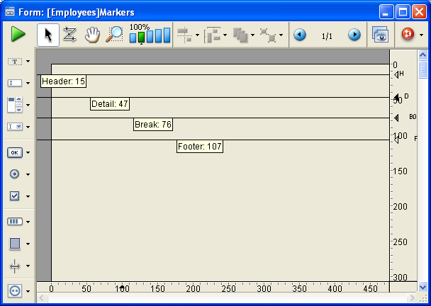
The Form editor always starts with the original control lines, labeled H, D, B0, and F.
B0 stands for “Break at level 0.” Level zero takes in all the records; it occurs after all the records are printed. Additional Break control lines are designated with numbers. A control line labeled B1 stands for “Break at level 1.”
A level one Break occurs after the records grouped by the first sorted field are printed.
| Label | Explanation | Prints after groups created by: |
| B1 | Break at level 1 | First sorted field |
| B2 | Break at level 2 | Second sorted field |
| B3 | Break at level 3 | Third sorted field |
H stands for “Header,” which is printed at the top of each page. Additional Header control lines are associated with Breaks. H1 stands for “Header at level 1.” A level 1 Header is printed just before the records grouped by the first sorted field are printed.
| Label | Explanation | Prints before groups created by: |
| H1 | Header at level 1 | First sorted field |
| H2 | Header at level 2 | Second sorted field |
| H3 | Header at level 3 | Third sorted field |
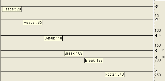
You create additional control lines by holding down the Alt key (Windows) or Option key (Mac OS) while clicking the appropriate control marker. You use a Break control line to create a Break area for the designated level. You use a Break Header control line to create a Break Header area at the designated level. The new line is positioned behind the existing control line; to see the new control line, you need to drag the existing line off of it.
If you use the Subtotal function to initiate Break processing, you should create a Break area for every level of Break that will be generated by the sort order, minus one. If you do not need anything printed in one of the Break areas, you can reduce its size to nothing by placing its marker on top of another control line. If you have more sort levels than Break areas, the last Break area will be repeated during printing.
The figure below shows additional control lines:
To delete Break or Break Header control lines that you have created, hold down the Ctrl key (Windows) or Command key (Mac OS) then click on the Break, Break Header, or label of the control line that you want to delete.
4D deletes the control line and, if necessary, renumbers the remaining lines.You cannot delete the original control lines H, D, B0, and F .

Product: 4D
Theme: Output forms and reports
4D Design Reference ( 4D v16)
4D Design Reference ( 4D v16.1)
4D Design Reference ( 4D v16.3)


